Starter Keyboard Tutorial: Buttons & Pins
Ready to go?
You should have already gone through the software setup section, setup the required software, downloaded the latest code from the Alt Ctrl Teensy Repository, and uploaded the starter keyboard code to your Teensy. Go ahead and open the starter-keyboard-teensy for the Teensy you are using.
Buttons and Pins
This default firmware was designed to run out-of-the-box. Simply upload it to your Teensy and you’ll be able to hook up buttons and make things happen! Later on we’ll look at how you can make simple changes to get more control over how it works, but for now, let’s just get it working.
It is important to make a mental connection between the pin numbers you will see referenced in code or in tutorials like this with the pin numbers on the Teensy board itself. When you first got your Teensy it may not have had any legs (little metal prongs), so the pin numbers refer to the holes along the sides of the board. This Teensy Pinout Chart (Links to an external site.)Links to an external site. shows you what pin numbers are associated with what holes and features. Print it out if you don’t have a hard copy and reference it as we go on.
There are three kinds of pins that we will cover right now. Ground (or GND or common), Digital Pins, and Touch Sense Pins. Each button will have to have one connection to ground, though they can all use the same one. In fact, anytime a component needs a connection to ground, it can connect with other ground wires (as long as one wire eventually gets to the ground on the Teensy). Ground provides a common low reference, usually zero volts. You can also think about it as LOW or off or false.
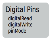
The second and final connection every button must have is a Digital Pin. This provides two things: first, HIGH voltage level that is the opposite of ground. Think of it as HIGH or on or true. Second, it provides a way to ask what the current state of the button is. In the code, we can ask the pin if it is HIGH or LOW.
As you can see, we can tell what pins can act as Digital Pins by looking for pin numbers that have a blob of gray around them. These are all the pins we can hook up to and get a button to work!
Tip: Pins can have multiple capabilities, some have multiple blobs of color to indicate what jobs they can perform, but we decide what job they do perform.
Finally, we have Touch Sense Pins which are labeled in yellow. Notice that every touch pin is also a digital pin.
image::teensy-touch-pin-key.png[Touch Pin Key, 200] image::teensy-touch-pins.png[Touch Pins, 200]
To start, we only care about getting a regular button working, so the only reason I want you to pay attention to the touch pins is to ignore them. Once you have uploaded the default firmware, you can hook a button up to any digital pin that isn’t also a touch pin and it will just work! In that image above, you can see that 0 and 1 are touch pins, but 2 isn’t. That means 2 is a perfect pin to connect to!
FYI: It is very easy to set the firmware to let you use all digital pins for buttons and ignore touch sensing, it just isn’t necessary for now.
Testing and Debugging
So you want to know that your button is working? You’re in luck! The surest way to know is by opening up the Serial Monitor in the Arduino software.
Tip: If you want a list of every digital pin you can use and the key presses they send by default, jump down to the end of this tutorial. You should really have a button hooked up for this section!
-
Make sure the Teensy is connected to the computer and Arduino has the starter-keyboard-teensylc.ino code open.
-
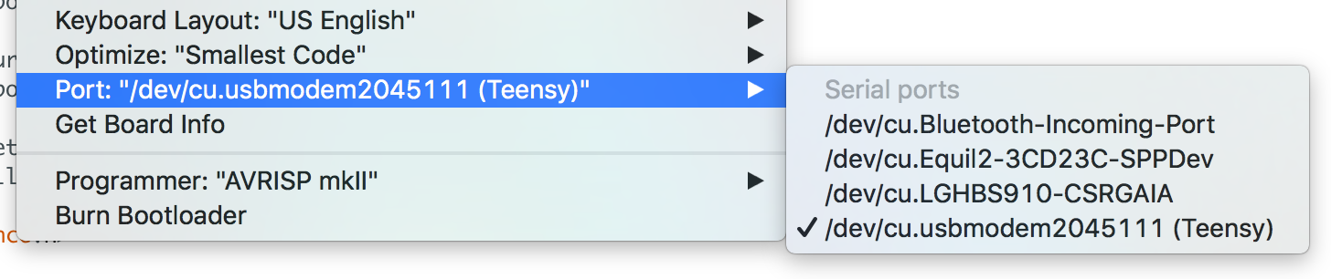
Click Tools on the toolbar and scroll down to Port. This is to make sure the Teensy is selected so we can talk to it.
-
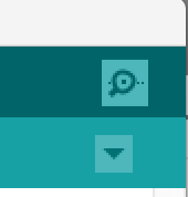
There are two ways to open the serial monitor. You can click Tools again and select Serial Monitor, or you can click the small magnifying glass in the upper right-hand corner of the Arduino software.
-
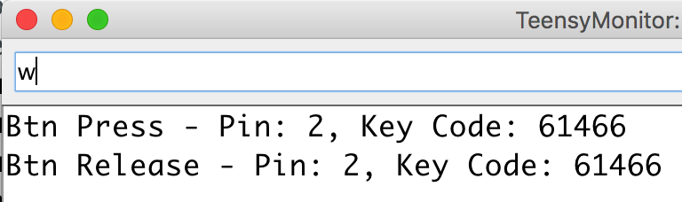
Once it is open, simply press and release the button you have connected. It should print out whenever you press and release and tell you what pin it is connected to so you can make sure which button is working. The Key Code is the raw value of the keyboard key (in this case representing w), but you can safely ignore that.
Of course, the other way to test your button is to simply open a text file, press the button, and see if it does what you expect. Some buttons are set to letters so will print a character, but others are arrow keys (which will move the cursor) or other less obvious key presses. The method above is the most foolproof!
Warning: If you have buttons hooked up that send key presses, they can accidentally change your code! Make backups and be careful not to have Arduino as the focus when testing.
Default Button Pins To make things easier, here is a list of every digital pin that you can hook buttons up to without any changes and the key presses they will generate.
Tip: If you want to change the keys that buttons press, or just to learn more, proceed on to Keyboard Firmware Tutorial - Part 2!
kbd:[W]
| Pin # | Key Press |
|---|---|
2 |
kbd:[W] |
5 |
kbd:[A] |
6 |
kbd:[S] |
7 |
kbd:[D] |
8 |
kbd:[Z] |
9 |
kbd:[X] |
10 |
kbd:[Up Arrow] |
11 |
kbd:[Left Arrow] |
12 |
kbd:[Down Arrow] |
13 |
kbd:[Right Arrow] |
14 |
kbd:[Space] |
20 |
kbd:[Enter] |
21 |
kbd:[Esc] |
Pin # = Key Press
2 = W
5 = A
6 = S
7 = D
8 = Z
9 = X
10 = UP ARROW
11 = LEFT ARROW
12 = DOWN ARROW
13 = RIGHT ARROW
14 = SPACE
20 = ENTER
21 = ESCAPE